![[Home electrician market] JM00001 FLINT RP2040-Grove Board](http://btoshop.jp/cdn/shop/products/logoon_855x700.png?v=1674097650)
![[Home electrician market] JM00001 FLINT RP2040-Grove Board](http://btoshop.jp/cdn/shop/products/IMG_3800-2048x1813_791x700.jpg?v=1674097650)
![[Home electrician market] JM00001 FLINT RP2040-Grove Board](http://btoshop.jp/cdn/shop/products/IMG_3801-2048x1885_761x700.jpg?v=1674097650)
![[Home electrician market] JM00001 FLINT RP2040-Grove Board](http://btoshop.jp/cdn/shop/products/DSC01746-2048x619_2048x619.jpg?v=1674097650)
![[Home electrician market] JM00001 FLINT RP2040-Grove Board](http://btoshop.jp/cdn/shop/products/DSC01760-2048x1144_1254x700.jpg?v=1674097650)
![[Home electrician market] JM00001 FLINT RP2040-Grove Board](http://btoshop.jp/cdn/shop/products/IMG_3069-2048x1536_934x700.jpg?v=1674097650)
![[Home electrician market] JM00001 FLINT RP2040-Grove Board](http://btoshop.jp/cdn/shop/products/RP2040-Grove_Board_pin_492x700.png?v=1674197584)
[Home electrician market] JM00001 FLINT RP2040-Grove Board
*This product is sold on consignment.
Bit Trade One will handle any inquiries regarding orders, shipping, etc.
Any inquiries regarding the product itself will be handled by the manufacturer.
Author: FLINT - mailto: flint@wonder-electronics.biz
Author's page
https://flint.works/p/flint-rp2040-grove-board/
overview
The Raspberry Pi Pico compatible RP2040 is equipped with a Grove connector, making it a USB dongle-type case. This stylish case allows you to develop in style without exposing the board.
Grove power supply 5V/3.3V switchable (switch type)
The Grove signal line has a built-in logic level converter (using BSS138) that supports both 5V and 3.3V signal lines (switchable with solder jumpers).
The Grove connectors can be switched between I2C, analog IN, DIO, and UART (switchable with solder jumpers).
When used with Arduino, a red LED is assigned to pin IO25, a full-color LED WS2812B-2020 is assigned to pin IO19, and a tactile switch is assigned to pin IO11. These can be used for debugging, etc.
The default settings are 5V power supply, 3.3V signal line, and I2C (specifications of M5Stack's 4-pin expansion unit).
Voltage Switching
Grove terminals are a mix of 5V and 3.3V systems, so you need to check what voltage system the device you are connecting is. For example, some devices have a 5V power line and a 3.3V signal line. (M5Stack's 4-pin expansion unit has this specification.)
The power line is switched using the slide switch on the board.

The RP2040 operates at 3.3V, so if you connect it directly to the Grove terminal, the signal line voltage will be switched to the 3.3V system.
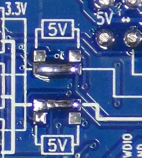
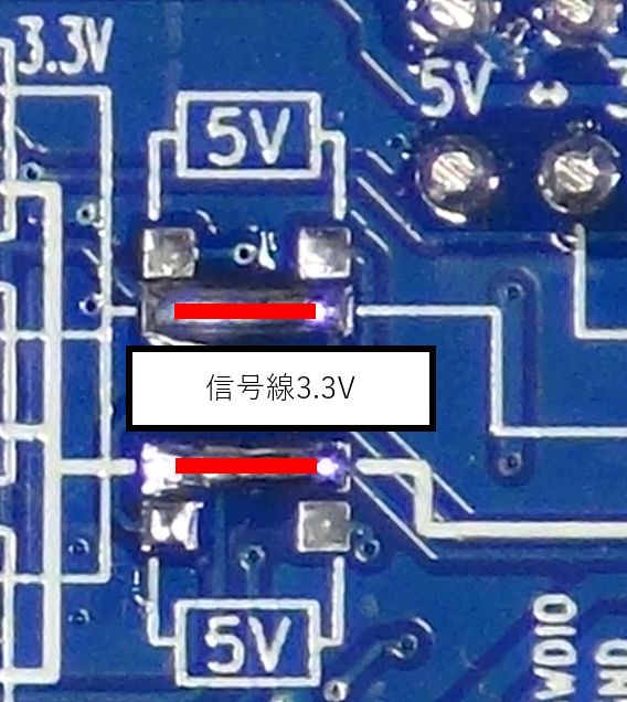
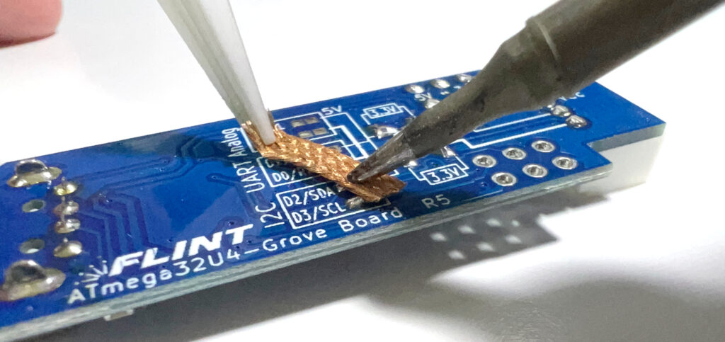
If you connect the solder jumper as shown below, the voltage will go through the level converter, be converted to a 3.3V system, and be connected to the Grove terminal.
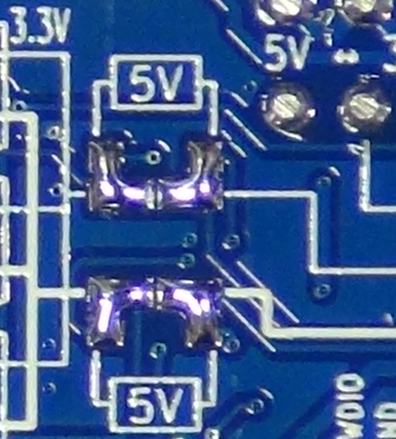
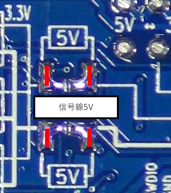
*After soldering, please check that all pads are not shorted out.
Signal line switching
Solder jumpers are used for the signal lines as follows depending on the application.

*If you want to input an analog signal into a microcontroller, passing it through a level converter may prevent accurate AD conversion.
How to remove solder jumpers
Remove the solder jumpers cleanly using a solder wick or similar. If you are not confident, practice on an unused board first.
How to remove the Grove connector
Pulling out the Grove terminal by holding the wire can easily result in poor contact, so you should either pull out the terminal by holding the case with your fingernails or use a special tool.
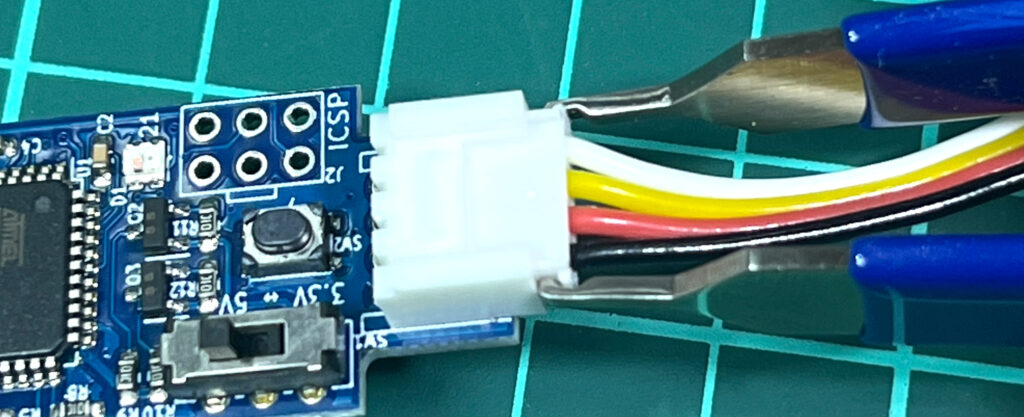
The ENGINEER SS-10 is a useful special tool.
How to open and close the case
Place it in the case like this and close the lid. Apply a little oil to the hole with a toothpick and wipe off any excess oil with tissue to make it easier to open again.
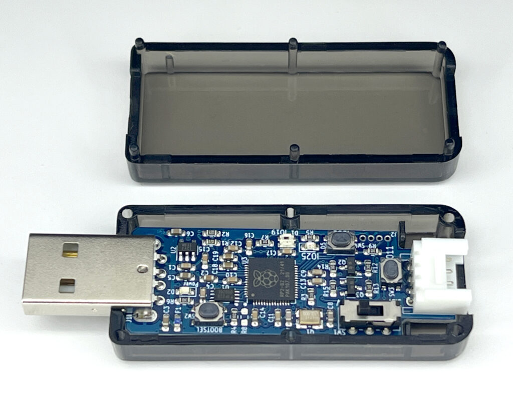
It takes some skill to open it. Insert a flathead screwdriver and pry it open. Once you have a gap, insert the screwdriver from both sides to widen the gap. This will scratch the case, so do it carefully. 

specification
- USB connector: USB-A
- Power supply: 5V (supplied from USB-A terminal)
- Display: LED (Power/RX/TX/IO25/full color)
- Size: 66mm x 24mm (including USB and case)
For detailed specifications, please visit the author's page
https://flint.works/p/flint-rp2040-grove-board/